
1.0 Overview
Driving Simulator (aka DS) is a plug-and-play development kit for creating four-wheel-drivable vehicle physics simulations.
Its main goal is to reproduce the most popular vehicle simulation style used in the game industry.
DS provides a simple yet robust solution for creating semi-arcade vehicle physics.
What problem does it solve?
Implementing vehicle physics from scratch can be extremely complex and time-consuming.
Developers often face challenges in stability, performance, and physical accuracy.
DS eliminates these obstacles by providing a ready-to-use solution that delivers high-fidelity vehicle physics with stable behavior and efficient resource usage.
1.1 Key Features
- High performance — core simulation is implemented in C++ for fast computation;
- Highly configurable — parameters are based on real-world vehicle data, allowing you to create everything from production cars to racing prototypes;
- Stable and detailed physics — supports realistic behaviors such as drifting, donuts, and high-speed driving.
1.2 Physics Features:
Engine
- Inertia
- Rev limiter frequency
- Engine braking torque
- Idle behavior
- Auto-blip
- Torque curve support
- Turbo kit supports with parameters such as maximum boost, wastegate level, and reference RPM
Differentials
- Inter-axle and inter-wheel limited-slip differentials
- Acceleration and deceleration sensitivity settings
- Inter-wheel differential preload torque
Clutch
- Maximum clutch torque
- Minimum and maximum reference engine RPM for smooth engine–transmission coupling
- Special clutch profiles to smooth gear shifting
Simulation Stability
- Sub-stepping support for improved stability at low frame rates
- Predictable behaviour at high speed
Suspension
- Camber angle
- Toe angle
- Spring length and attachment points
- Spring stiffness and damping
- Caster angle, kingpin angle, and stub length for realistic nonlinear wheel movement
- Bump stop implementation prevents excessive wheel penetration into the vehicle body and improves weight distribution behavior
- Anti-dive controls how much the vehicle’s front end compresses during braking
- Anti-squat controls rear suspension compression during acceleration
Tires
- Friction circle
- Pneumatic trail (self-aligning torque)
- Tire relaxation simulation
Aerodynamics
- Two points lift sources(the front and rear of the car)
- Drag force
- Relative world wind source
Assistances
- Input assistance system for enjoying power slides
- ABS and TCS implementation
1.3 Demo/Lite/PRO
There are two versions of the plugin - PRO and Lite. Both of these versions use the same physics model and settings.
The Demo was made entirely on the Lite version of the plugin without using any additional features. The Demo has a time limit of 15 minutes, after which you need to restart it.
Version features | Lite | PRO |
|---|---|---|
Physics | ⏺ | ⏺ |
CarUnit Settings | ⏺ | ⏺ |
No limit on the number of vehicles | ⏺ | |
Multithreading | ⏺ | |
”Contact Point” & ”Modifiable Contact Pair” | ⏺ |
Supported platforms | Lite | PRO |
|---|---|---|
Window | ⏺ | ⏺ |
Mac | ⏺ | ⏺ |
Linux | ⏺ | ⏺ |
Android | ⏺ | ⏺ |
iOS | ⏺ | ⏺ |
2.0. Quick Start
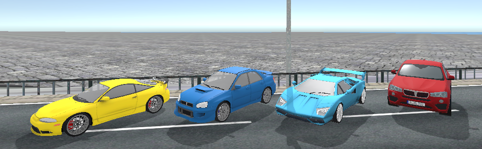
QuickStart scene contains 4 cars ready to use. To select them use F1-F4.
To control cars we use the NslDemo_CarController script.
2.1. QuickStart scene hierarchy
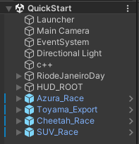
QuickStart scene hierarchy (Pic.1):
- Launcher - contains the NslDemo_QuickStartLauncher component, the main controller of the demo scene. Activates one of 4 cars;
- Main Camera - will follow the target car;
- EventSystem - contains a new InputSystem component;
- Directional Light - a standard scene Light;
- C++ GameObject contains 2 NslDemo components:
- NslGlobalAerodynamics - mandatory component containing global aerodynamic settings;
- NslRuntimeDebug prints c++ log messages to Unity’s debug console.
- RiodeJaneiroDay - 3d models of the scene;
- HUD_ROOT - UI canvas;
- Azura_Race, Toyama_Export, Cheetah_Race, SUV_Race - 4 demo cars.
2.2. Car Creation
General phases:
- Create GameObject (root) with a specific hierarchy or instantiate DummyCar;
- Put and properly locate 3d model of the car, body collider, wheels;
- Link all Transforms to NslCarRoot;
- Create CarUnits Settings or use predefined;
- Link all CarUnits Settings to NslCarRoot;
- Create scripts to control NslCarRoot. As an example, see the predefined NslDemo_CarController script
2.3. Initial Car Adjusting
GameObject structure
Properly structured Transformers are necessary for normal operation of DS-Asset. We need 3 parts:
- Root GameObject that has NslCarRoot component;
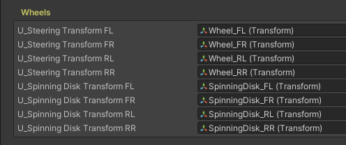
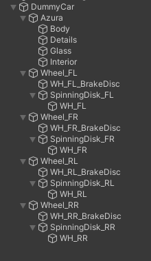
- 4 Transforms for wheel mounting. The front axle will be controlled using the steering wheel (rotation around the Y-axis). The rear axle cannot rotate. Wheel_FL/FR/RL/RR in Pic.1;
- 4 Transforms for disk mounting (rotation around the X-axis). SpinningDisk_FL/FR/RL/RR in Pic.1.
Quick start
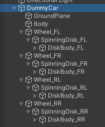
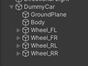
To speed up the process of creating GameObjects, you can create a pre-structured GameObject (DummyCar) (Pic.1) using the HierarchyMenu ➡ NSL ➡ “Create Dummy Car” button (see ).
DummyCar contains:
- NslCarRoot and Rigidbody components in the root GameObject;
- GroundPlane – Temporary plane at the point (0,0,0) that can be deleted and is used to determine the position of the car body relative to the ground;
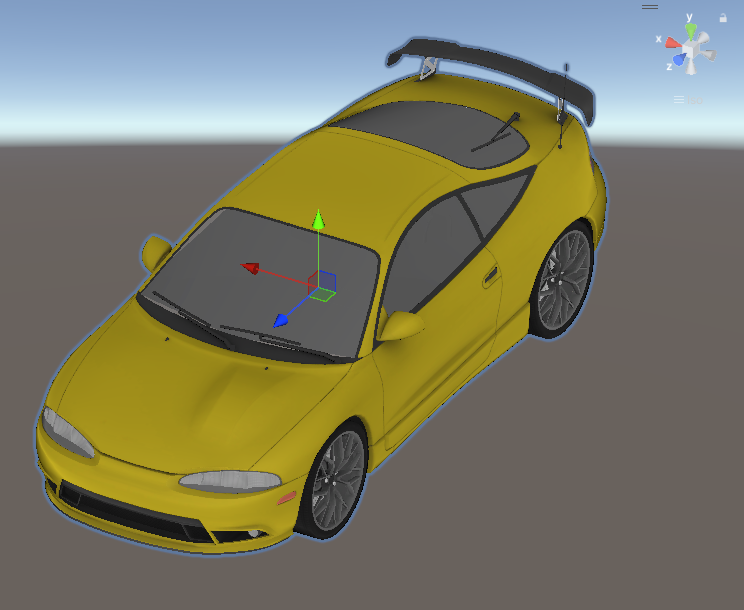
- Body – GameObject represents a solid car body. It has a BoxCollider component. Instead of this GameObject, you should put your own 3D model of the car and position the Collider correctly (see Using own 3D-model section);
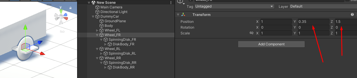
- Wheel_FL/FR/RL/RR – GameObjects represent the position of the wheel attachment relative to the car body (Pic.2);
- SpinningDisk_FL/FR/RL/RR – GameObjects under corresponding Wheel_FL/FR/RL/RR GameObjects represent the spinning disks. They must be placed at the point (0,0,0).
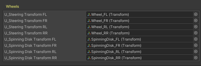
Be aware that the NslCarRoot component must be correctly linked with the wheel Transforms (Pic.3).
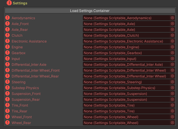
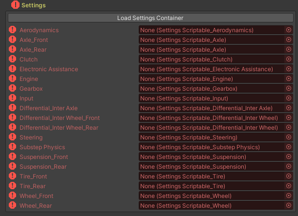
Be aware that by default the NslCarRoot doesn’t have any linked Settings (Pic.4). How to set up CarUnit Settings please see the Car Settings section.
For more information see the NslCarRoot section.


2.4 Using own 3D-model
- First of all, your 3D model must be adapted to Unity's 3D coordinate system. This means that the direction of the right axis of your 3D model must match the direction of the right axis in Unity 3D, and the same applies to the other axes.
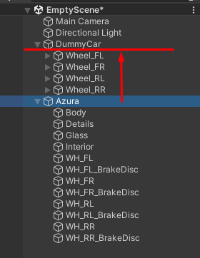
- Drag your model prefab into the scene. Let's replace the body of your car.
- Unfold the gameobject “DummyCar”.
- “GroundPlane” - a temporary plane at the point (0,0,0) that can be deleted and is used to determine the position of the car body relative to the ground.
- Instead of the “Body”, you should place your 3D car model.
- Delete the “GroundPlane” and ‘Body’ game objects from “DummyCar” (optionally).
- Unpack the model prefab completely so that it becomes editable. To do this: right-click on the finished model ➡ Prefab ➡ Unpack Completely.
- Drag the unpacked gameobject under the “DummyCar” hierarchy.
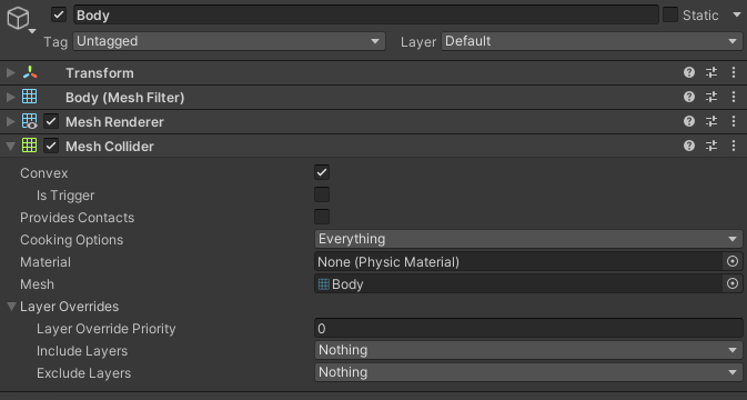
- Select the “Body” gameobject in the “Azure” hierarchy and add a ‘MeshCollider’ to it. Enable the “Convex” option. Now we have a primary collider for the car.
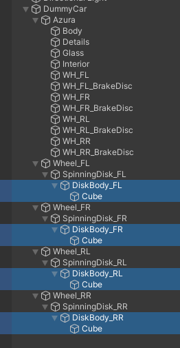
- The next step is to attach the wheels. Expand the original wheel gameobjects and delete the wheel templates from them. In the following screenshot, game objects have been selected for deletion.
- As you can see, the wheel transforms are already binded. We will use the existing transforms, simply adjusting their origin positions to match our new model. To do this, we will simply copy the model's wheel positions to the corresponding wheel initial transforms.
- The wheel placeholders have been set up. Now we need to properly put the wheels from our 3D model. The wheel rim and tire should be placed under the transformation that was set in the “U_Spinning Disk Transform XX” field. And the brake disc should be placed under the transformation that was set in the “U_Steering Transform XX” field.
- After rearrangement, the hierarchy will look as follows:



2.5. Configuring the inertia tensor
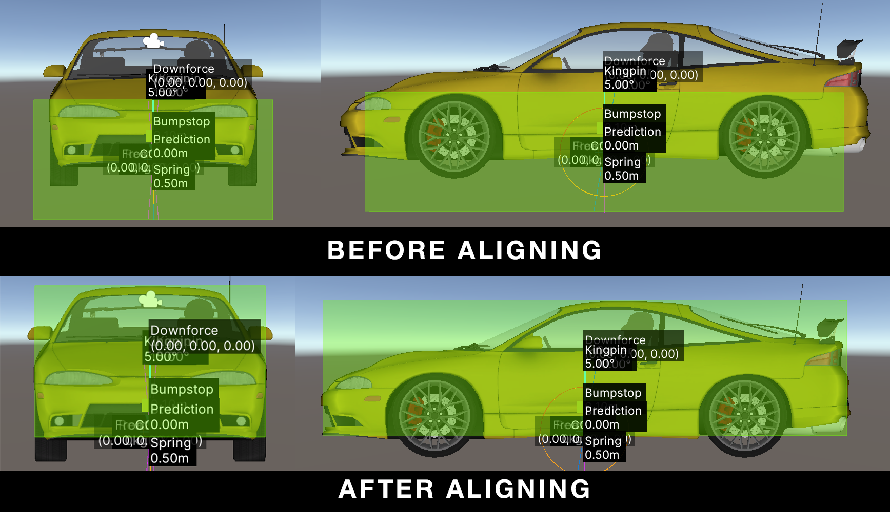
- Select the created “Substep Physics” setting. Here we use two specific fields, “Rigidbody Size” and “U_Rigidbody_Size_Gizmos_Offset” to configure the inertia tensor.
“Rigidbody Size” is used to determine the dimensions of the virtual cube, which should replicate the shape of the vehicle body.
“U_Rigidbody_Size_Gizmos_Offset” is used to adjust the display of the cube volume. This field is not used in physical calculations; it is only used for virtual display to align the cube volume with the vehicle body volume.
- Let's take a look at the suspension settings. They include a field called “RightWheelMountOffset,” which has a default value of zero. This value determines the mirrored position of the wheels relative to the x-axis. The easiest way to adjust the position of the wheels is to copy the position of the right front and rear wheels to the corresponding suspension settings.
- Now the wheels are attached correctly.
- If necessary, you can adjust the wheel radius in the wheel settings.
2.6 Assign Car Settings
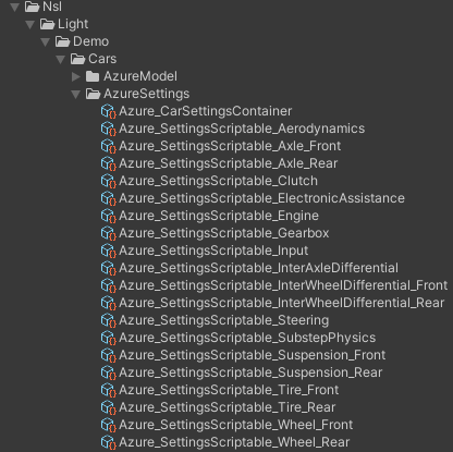
One of the purposes of NslCarRoot is to be a CarUnits settings container (Pic.1). Each CarUnit is responsible for a specific logic and has the corresponding settings (ScriptableObject file) (Pic.2).
CarUnit settings can be created individually or all at once with a single click (see ).
CarUnit settings can be grouped into a container - NslCarSettingsContainer. Quick start: We can assign all CarUnits Settings with a single click NslCarRoot ➡ Settings section ➡ “Load Settings Container”. The window contains all possible SettingsContainers in the project (see ).
2.7 Before Launch
Simply, NslCarRoot has several purposes:
- Container of CarUnits settings that will be transferred to the C++ level;
- Container of data that are used between Unity and the C++ level (the DataStructs section contains all data structs used for communication).
- Contains methods for communication between Unity and the C++ level.
Be aware that NslCarRoot doesn’t implement Unity’s FixedUpdate method. For this we have the NslCarRoot::ExecuteFixedUpdate method that is called outside.
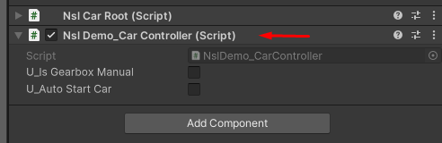
- Add the NslDemo_CarController component to the same GameObject as the NslCarRoot (Pic.1). It enables/disables CarBrain, passes Unity’s FixedUpdate event, implements simple manual/automatic transmission logic and passes input data. Check the “Auto start car” box.
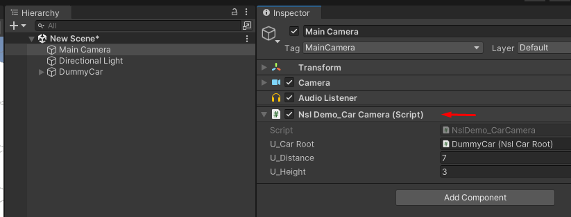
- Add the NslDemo_CarCamera to camera GameObject. This script follows the target car (Pic.2).
3.0 Tuning Tips
3.1 Understeering and Oversteering
To describe the approach to quick and effective car tuning, we will use two basic terms: understeer and oversteer. These two terms describe a tendency toward excessive maneuverability or, conversely. These characteristics can manifest themselves during various driving conditions: braking, acceleration, or cornering.
But what does it mean indeed?
In fact, it is simply the balance of traction between the front and rear axles. When the front wheels lose traction, it is called understeer, and when the rear wheels lose traction, it is called oversteer.
When the tires generate lateral (side) forces, these forces act on the car’s center of mass through a lever arm, creating a rotational torque. This torque causes the car to rotate, aligning one end of the vehicle toward the direction of the force generated by the tires.
If the dominant torque is produced at the front axle, the car tends to rotate more sharply than intended, resulting in oversteer. Conversely, if the dominant torque is generated at the rear axle, the effect is opposite, leading to understeer.
Listed below are the most common factors that affect a vehicle's handling:
SETUP | KEY IMPACT | UNDERSTEERING | OVERSTEERING |
CG Height | High CG Height during cornering can cause uneven load between wheels where outside wheels take an excessive load which they can't fully handle and inside wheels become underloaded. | The higher CG placement can cause understeering during acceleration.
| The higher CG placement can cause oversteering during deceleration.
|
Front-rear bias of the CG | Defines the initial mass distribution between front and rear axle. | The bias of the cg towards the front axle increases the load on the front axle and decreases on the rear axle. | The bias of the cg towards the rear axle increases the load on the rear axle and decreases on the front axle. |
Spring Rate | Increases the response to load. A stiffer suspension spring increases the difference between the load on the outer and inner wheels when cornering. The outer wheels receive more load than the inner wheels. | A stiffer suspension on the front axle results in uneven load distribution across the wheels when cornering. This causes one wheel to be overloaded while the other is underloaded, which reduces the overall load on the axle. | The effect will be the opposite if a stiffer suspension is installed on the rear axle. |
Anti-roll Bar Rate | It reduces body roll, which evenly distributes the load on the axle. | A stiffer anti-roll bar on the front axle makes the car more prone to understeer. | A stiffer anti-roll bar on the rear axle makes the car more prone to oversteer. |
Damping (Rebound/Compression) Rate | It reduces the suspension's response to road unevenness and helps maintain the body's resistance to roll, but the suspension's slow response may reduce the load on the wheels. | Stiffer shock absorbers on the front suspension make the car more prone to understeer. | The effect will be the opposite if stiffer shock absorbers are installed on the rear axle. |
Min Spring Length to Bumpstop | The bumpstop acts as a limit to the suspension's travel, preventing it from penetrating inside the vehicle body. The bump stop instantly pushes the vehicle body away, preventing excessive penetration. This feels like a sudden impact, which can cause fluctuations in the load on the wheel. | Values close to the maximum spring length will cause the axle to constantly bounce off the ground, which means there will be no constant load. The understeering can be reproduced if this scenario is implemented on the front suspension. | Lower values mean that the bump stop will engage much less frequently. In this case, the suspension may be subjected to extreme load at the moment of impact, which could lead to unstable vehicle handling. Unstable handling will occur if a sudden impact is applied to the front suspension. |
Anti Dive/Squat Percent | Anti dive minimizes the nose-diving of the front end that occurs during braking by using suspension's forces to counteract weight transfer. Anti squat prevents from squatting the rear end of vehicle under acceleration, by using torque forces to lift the chassis counteracting weight transfer. | Low anti-squat values make the car more prone to understeering during acceleration. | Low anti-dive values make the car more prone to oversteering during deceleration. |
The point of application of aerodynamic lift. | In the current implementation of the physics engine, the lift force (downforce) acts on a virtual point. Depending on which end of the car the force is applied to, the weight will be transferred to the corresponding end of the car. | If the point at which the downforce is applied is closer to the rear axle, this can result in understeering. | If the point at which the downforce is applied is closer to the front axle, this can result in oversteering. |
Toe Angle | Shifts the initial tire slip angle, which typically influences the occurrence of self-aligning torque (SAT) | Small amounts of toe-in increase understeer in both the front and rear suspensions. However, the understeer effect may be more pronounced in the front suspension due to its ability to maintain a smaller slip angle when the steering wheel is turned. | A slight increase in toe increases oversteer in both the front and rear suspensions.
|
Brake Balance | Excessive braking torque acting on the wheels can cause them to lock up. | If the braking force is applied more heavily to the front wheels, this will result in understeering. | If the braking force is applied more heavily to the rear wheels, this will result in oversteering. |
Open and Locked Differential | An open differential always distributes the torque transmitted from the transmission to the wheels equally between the two wheels. A limited-slip differential always distributes the torque transmitted from the transmission to the wheel with the greatest load. | Rear wheels drive: An open differential on the rear axle can lead to understeer when cornering, as the inside wheel experiences underload and the outside wheel experiences overload. The underloaded wheel spins too much and fails to maintain traction. At the same time, the opposite wheel does not slip and experiences excessive load, which allows it to generate additional traction and prevent the car from skidding. Front wheels drive: Locked differential can cause both wheels to slip longitudinally during acceleration, which can completely negate the tire’s lateral stiffness. This can lead to sharp understeer. | Rear wheels drive: Locked rear-axle differential can cause oversteer when cornering. Despite differences in wheel conditions, a locked differential tends to equalize the amount of slip on both wheels. Front wheels drive: An open differential on the front axle works the same way as one on the rear, but in this case, the outer wheel — which remains overloaded when cornering — provides traction on the front axle. This cannot cause oversteer, but an open differential allows for more freely cornering, unlike a limited-slip differential. |
3.2 Slip Length
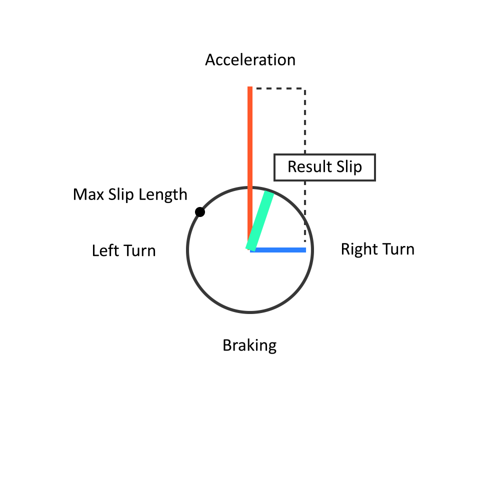
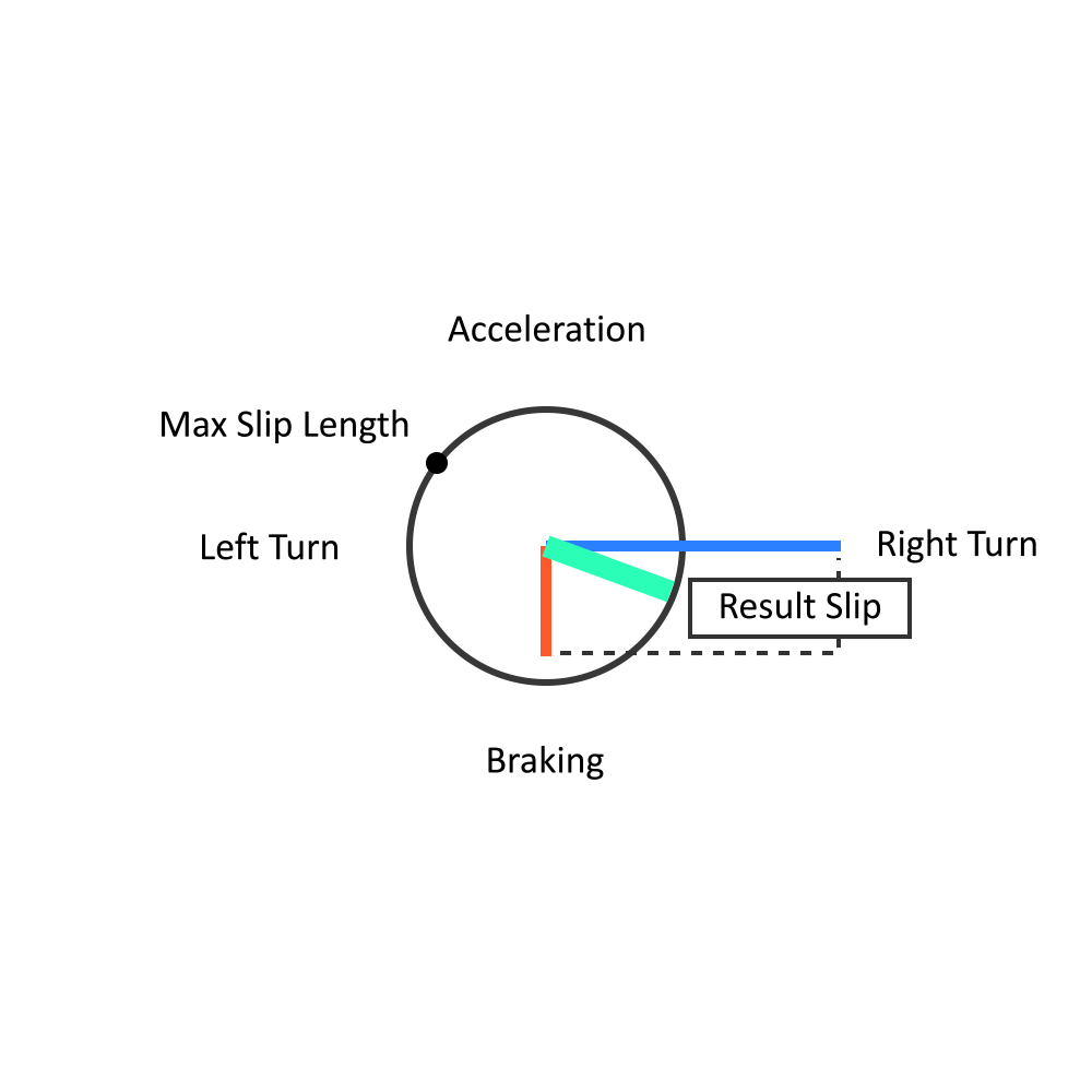
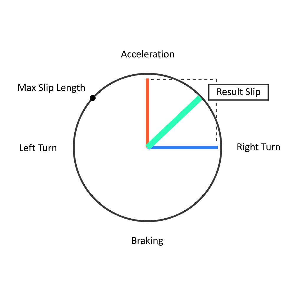
Slip length is the key value of the tire settings. It defines the maximum of normalized slip length. By default it equals 1.0.
What does this mean in practice? A tire cannot withstand both longitudinal and lateral slip at the same time. The weaker direction of slip will be suppressed by the stronger one. This directly affects how the tire generates longitudinal and lateral forces.
Let's look at a few examples:
- When accelerating from a standstill, the tyre experiences significant longitudinal slip. In this case, the longitudinal slip almost completely suppresses the lateral slip and, as a result, reduces the lateral force. This can lead to excessive oversteer in powerful rear-wheel-drive cars.
- The car is drifting sideways. In this case tires are experienced by a huge lateral slip, which almost completely suppresses a longitude slip. It leads to a non responsive braking or accelerating during the power slide.
- The vehicle is driving in normal conditions. Longitudinal and lateral slip do not exceed their peak values. In this case, the slip does not normalize, and the tyre can simultaneously generate maximum longitudinal and lateral forces.

Increasing or decreasing the slip length allows you to widen or narrow the range within which normalisation will be performed.
3.3 Nominal Load
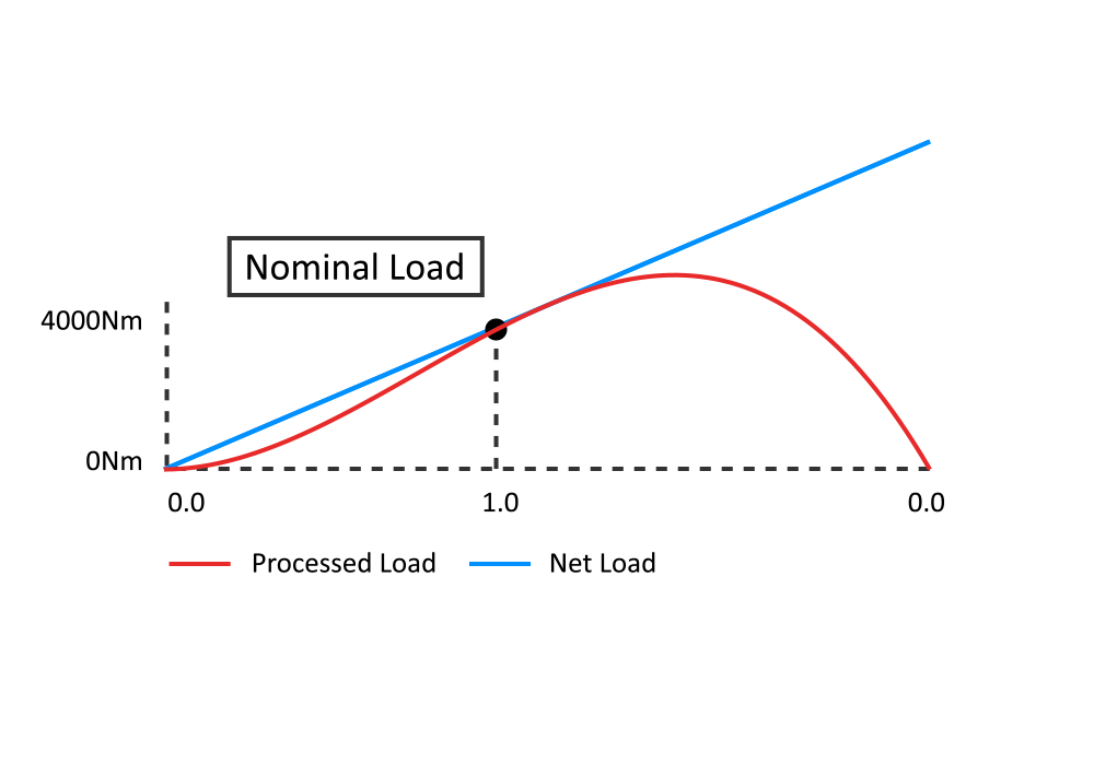
The main feature of the tire is that it cannot sustain the same load when the load is increased. In tire settings are used two parameters: nominal load and load friction factor for longitude and lateral force. These two parameters determine how the tire will respond to the load.
Pic. 4 shows how the tire responds to a linear increase in load. It can be observed that the load does not increase in line with the net load. At some point, the tire will no longer be able to withstand the load, which corresponds to the net load.
4.0 Gizmos
The suspension system is one of the key elements of a car's handling. Depending on how you set it up, the car will behave differently.
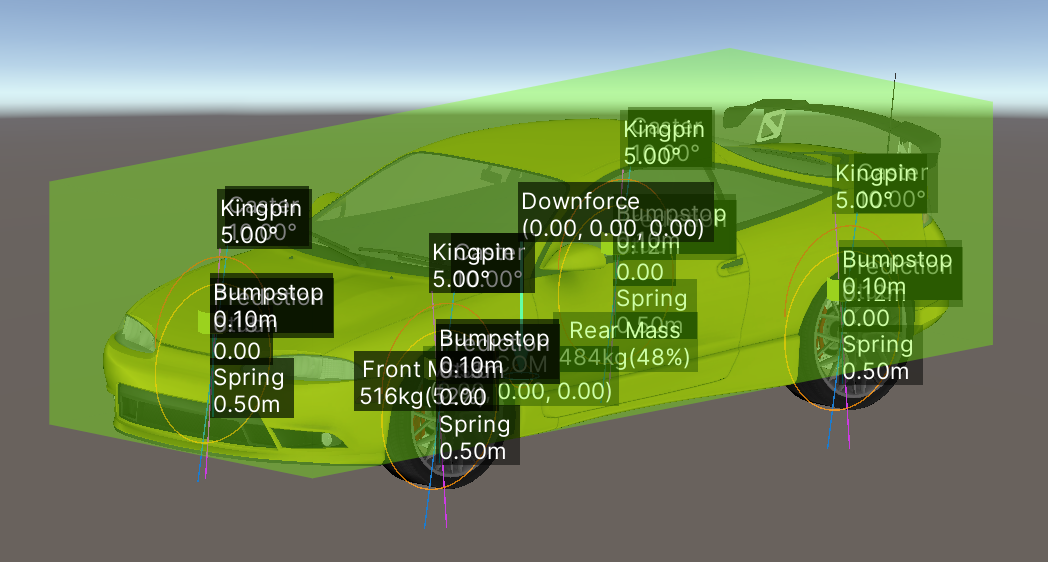
Gizmos is a visual assistant that allows you to immediately see the current Suspension Settings (Pic.1).

To change the color of the Gizmos, open the menu: TopMenu ➡ Edit ➡ Preferences ➡ Nsl (see ).
To enable/disable specific Gizmos drawing open the menu: #Scene ➡ ⋮ ➡ ”Overlay Menu” ➡ ”Show Nsl Gizmos” (see).
Tip: Press the backtick key (`) anywhere in the scene viewport to open the “Overlays Menu”.
5.0 Rigidbody
The Rigidbody component will be automatically added to the same GameObject where the NslCarRoot component is located.
Be aware that the UseGravity field must be unchecked. All gravity logic is calculated at the C++ level by the DS plugin.
Be aware that for the car to behave correctly, the “Drag” and “Angular Drag” fields must have a value of 0.
6.0 Scripts
6.1 NslCarRoot
NslCarRoot is the main component that must be placed on the root GameObject.
On the same layer also must be Rigidbody (it will be automatically added via RequireComponent attribute).
NslCarRoot is a CarUnits Settings container and a bridge between C# and C++ levels (that are linked via DataIn/Out).
Debug

Enable passing regular messages from the C++ level to C#.
NOTE: NslRuntimeDebug component must be added to any GameObject to see.
Physics
Substeps
Number of physical sub-steps. Increasing the number of sub-steps breaks down the main physics cycle into sub-cycles with shorter time periods. One sub-step means that physics is performed in one cycle.
This approach improves the stability and accuracy of physics performance, especially at low frame rates or during high-speed movement.
Raycast
This block contains settings for wheel raycasts. The specified settings apply to all wheels equally.
Query Trigger Interaction
Controls whether the wheel's raycast will detect triggers or not.
Layer Mask
The layer mask is used to filter colliders that the wheel raycast can hit.
Settings

This block contains serializable fields with vehicle settings. Each field must contain the appropriate setting for initialization and physics startup.
Load Settings Container
A functional button that allows you to apply all car settings from CarSettingsContainer. Pressing the button opens a drop-down menu with a list of all CarSettingsContainers contained in the project.
Wheels

This block contains serializable fields with transforms to synchronize the visual movement of the wheels with the simulation results.
Steering Transform XX
For the assigned transform, the world position and world rotation of the steering movement are applied.
Spinning Disk Transform XX
Only local rotation of the spinning disc is used for the assigned transform.
💡The tip: The same transforms cannot be assigned as both a “Steering” and “Spinning Disk” transform. The most appropriate way to assign transforms is when the parent transform is “Steering" and the child transform is “Spinning Disk”.
6.2 Data structures
Data structures are the communication layer between your Unity code and the Driving Simulator native physics engine. Use this section to identify when each value is written or read, then refer to the grouped field reference for detailed telemetry.
InDataContainer→ExecuteFixedUpdate→OutData_Container→Unity reads telemetry- Write
InDataContainerbefore callingNslCarRoot::ExecuteFixedUpdate. - Read
OutData_Containerafter the call returns. Its values are from the final simulation substep. - Use
InRaycasterDataandOutRaycasterDataonly in the Unity physics bridge.
Inputs — write before the physics update
InDataContainer
Contains fields that must be filled with current input data before each NslCarRoot::ExecuteFixedUpdate call.
| Field | Type | Range | Meaning |
|---|---|---|---|
P00_Brake01 | float | 0–1 | Brake pedal: released to fully pressed. |
P01_Clutch01 | float | 0–1 | Clutch pedal: engaged to fully disengaged. |
P02_Handbrake | bool | — | Handbrake state. |
P03_Throttle01 | float | 0–1 | Throttle: released to fully pressed. |
P04_Steering11 | float | -1–1 | Steering: full left to full right. |
P05_TorqueBoost | float | -100–1000 | Additional engine torque multiplier (Nitro). |
Outputs — read after the physics update
OutData_Container
This container holds runtime telemetry. It is updated during every substep; after the update, read the values recorded in the final substep.
Position labels: FL = front-left, FR = front-right, RL = rear-left, RR = rear-right. Structures marked Front / Rear are available per axle.
Powertrain
OutData_Axle (Front / Rear)
| Field | Type | Meaning |
|---|---|---|
P01_BrakeDiscPressure01 | float | The input value of the brake pedal on the current axle. Range: [0...1]. |
P02_BrakeDiscTorque | float | The generated brake torque in Nm. This torque will be passed on each wheel on the axle. |
P03_HandbrakeTorque | float | The generated brake torque in Nm. This torque will be passed on each wheel on the axle, but is not modified by the ABS system. |
OutData_Chassis
| Field | Type | Meaning |
|---|---|---|
P00_WheelBase | float | The distance between the front and rear axles in meters. |
OutData_Engine
| Field | Type | Meaning |
|---|---|---|
P00_Rpm | float | Current engine RPM. |
P01_Torque | float | Torque generated by the engine and boost. |
P02_Throttle01 | float | The input value of the throttle. It can be adjusted using the rev limiter or the auto-blip device. |
P03_TotalBoost | float | The total torque multiplication factor provided by all installed boosts. |
P04_HasBoosts | bool | Is any boost installed? |
P05_Boost0 | float | The torque generated by the first boost installed. |
P06_Boost1 | float | The torque generated by the second boost installed. |
P07_Boost2 | float | The torque generated by the third boost installed. |
P08_Boost3 | float | The torque generated by the fourth boost installed. |
P09_IsRevLimiterWasActiveInStep | bool | Was the rev limiter enabled during the last sub-stepping cycle? |
P10_IsReverseAutoBlipWasActiveInStep | bool | Was the auto-blip enabled while reverse during the last sub-stepping cycle? |
P11_IsDownshiftingAutoBlipWasActiveInStep | bool | Was the auto-blip enabled while downshifting during the last sub-stepping cycle? |
P12_IsUpshiftingAutoBlipWasActiveInStep | bool | Was the auto-blip enabled while upshifting during the last sub-stepping cycle? |
OutData_Clutch
| Field | Type | Meaning |
|---|---|---|
P00_Inertia | float | The total inertia of the transmission up to this component and the inertia of the clutch in kilogram-square meters. |
P01_State01 | float | This value displays the current state of the clutch pedal. 0 - Clutch pedal fully released 1 - Clutch pedal fully depressed |
P02_StateIndex | int | The number indicates the current clutch status: -1 - Disengaged 0 - Slipping 1 - Engaged |
P03_ForwardTorqueToGearbox | float | The amount of torque that will be transmitted to the Gearbox. Depending on the state of the clutch, the transmitted torque will be generated differently: Disengaged - No torque will be transmitted at all. Slipping - Only the torque generated by friction between the engine and the transmission will be transmitted. Engaged - The clutch is fully engaged with the engine. Torque will be transmitted directly from the engine. |
P04_BackwardTorqueToEngine | float | Same as “P03_ForwardTorqueToGearbox,” but this is torque directed backward. |
OutData_Gearbox
| Field | Type | Meaning |
|---|---|---|
P00_Inertia | float | The total inertia of the transmission up to this component and the inertia of the gearbox in kilogram-square meters. |
P01_Torque | float | The torque transmitted out of the gearbox |
P02_CurrentGear | int | The index of the current active gear. -1 - reverse gear. 0 - neutral gear. 1, 2, 3, … - drive gear |
P03_CurrentGearRatio | float | The gear ratio of the currently selected gear. |
P04_TargetGearToShift | int | Shows the gear index when the transmission is in shift mode. Otherwise, it shows zero. |
P05_ShiftDirectionIndex | int | Shows the direction of gear shifting. -1 - downshifting. 1 - upshifting. 0 - shifting is not happening. |
P06_DirectionIndex | int | Shows the direction of the torque generated by the gearbox. -1 - reverse 1, 2, 3, … - drive 0 - neutral |
P07_IsInShiftingProcess | bool | Is the transmission in the process of shifting gears? |
P08_SettingsMaxGear | int | Maximum gear index of the gearbox. |
OutData_Input
| Field | Type | Meaning |
|---|---|---|
P01_ProcessedSteeringAngleInDeg | float | The steering angle in degrees processed by the input handler. |
P02_ProcessedSteeringAngleInRad | float | The steering angle in radians processed by the input handler. |
P03_ProcessedBrake01 | float | The brake pedal position processed by the input handler. |
P04_ProcessedClutch01 | float | The clutch pedal position processed by the input handler. |
P05_ProcessedHandbrake | bool | The handbrake state processed by the input handler. |
P06_ProcessedThrottle01 | float | The throttle pedal position processed by the input handler. |
P07_ProcessedSteering11 | float | The normalized steering state value in the range from -1 to +1, processed by the input data processor. |
P08_ProcessedTorqueBoost | float | The engine torque multiplier processed by the input handler. |
OutData_InterWheelDifferential (Front / Rear)
| Field | Type | Meaning |
|---|---|---|
P00_LeftWheel_RuntimeInertia | float | The total inertia of the transmission up to this component and the inertia of the inter-wheel differential. |
P01_LeftWheel_DriveTorque | float | The torque transmitted out of the inter-wheel differential to the left wheel. |
P02_RightWheel_RuntimeInertia | float | The total inertia of the transmission up to this component and the inertia of the inter-wheel differential. |
P03_RightWheel_DriveTorque | float | The torque transmitted out of the inter-wheel differential to the right wheel. |
OutData_RootDifferential
| Field | Type | Meaning |
|---|---|---|
P00_FeedbackRpm | float | The number of RPM entering the root differential. |
P01_GearedFeedbackRpm | float | RPM measured at the wheels. |
Vehicle body
OutData_Rigidbody
| Field | Type | Meaning |
|---|---|---|
P00_WorldAngularVelocity | Vector3 | The result of the calculation of the world angular velocity during the sub-step calculation. |
P01_WorldLinearVelocity | Vector3 | The result of the calculation of the world linear velocity during the sub-step calculation. |
Wheels, steering and suspension
OutData_Steering
| Field | Type | Meaning |
|---|---|---|
P00_Wheel_FL_SteeringAngleDeg | float | The steering angle in degrees calculated for the front left wheel, taking into account Ackermann geometry. |
P01_Wheel_FL_SteeringAngleRad | float | The steering angle in radians calculated for the front left wheel, taking into account Ackermann geometry. |
P02_Wheel_FR_SteeringAngleDeg | float | The steering angle in degrees calculated for the front right wheel, taking into account Ackermann geometry. |
P03_Wheel_FR_SteeringAngleRad | float | The steering angle in radians calculated for the front right wheel, taking into account Ackermann geometry. |
OutData_Suspension (Front / Rear)
| Field | Type | Meaning |
|---|---|---|
P00_LoadForce_LeftWheel | float | The load force acting on the left wheel. |
P01_LoadForce_RightWheel | float | The load force acting on the right wheel. |
P02_TrackWidth | float | The distance between the two wheels at the mounting point (TrackWidth = 2.0f * (RightWheelMountOffset.x + StubLength)) |
P03_ArbForce_LeftWheel | float | The anti-roll bar force acting on the left wheel. |
P04_ArbForce_RightWheel | float | The anti-roll bar force acting on the right wheel. |
P05_BumpStopForce_LeftWheel | float | The force generated upon impact with a bump stop and affects on the left wheel. |
P06_BumpStopForce_RightWheel | float | The force generated upon impact with a bump stop and affects on the right wheel. |
P07_SpringForce_LeftWheel | float | The force generated by the suspension spring when compressed on the left-hand side. |
P08_SpringForce_RightWheel | float | The force generated by the suspension spring when compressed on the right-hand side. |
P09_DampForce_LeftWheel | float | The force generated by the shock absorber on the left-hand side. |
P10_DampForce_RightWheel | float | The force generated by the shock absorber on the right-hand side. |
P11_RuntimeSpringLength_LeftWheel | float | The current spring length in meters on the left-hand side . |
P12_RuntimeSpringLength_RightWheel | float | The current spring length in meters on the right-hand side . |
P13_SuspensionForceToCom_LeftWheel | Vector3 | The vector of the net force in world space, generated by the suspension on the left side and acting on the center of mass. |
P14_SuspensionForceToCom_RightWheel | Vector3 | The vector of the net force in world space, generated by the suspension on the right side and acting on the center of mass. |
P15_SuspensionTorqueToCom_LeftWheel | Vector3 | The vector of the net torque in world space, generated by the suspension on the left side and acting on the center of mass. |
P16_SuspensionTorqueToCom_RightWheel | Vector3 | The vector of the net force in world space, generated by the suspension on the right side and acting on the center of mass. |
P17_SpringVelocity_LeftWheel | float | The current velocity of the spring displacement on the left-hand side. |
P18_SpringVelocity_RightWheel | float | The current velocity of the spring displacement on the right-hand side. |
P19_IsSpringCompressed_LeftWheel | float | Did the suspension compress during the last physical step on the left-hand side? |
P20_IsSpringCompressed_RightWheel | float | Did the suspension compress during the last physical step on the right-hand side? |
OutData_Tire (FL/FR/RL/RR)
| Field | Type | Meaning |
|---|---|---|
P00_SlipLength | float | This value allows us to track the performance of the tire: value < max slip length — tire generates forces without normalizing. value == max slip length — tire produces the maximum performance without losses. value > max slip length — tire is affected by excessive sliding which leads to normalizing forces and loss of tire performance. "max slip length" refers to "TireSettings"->"SlipLength". |
P01_LongitudeForceUsage | float | This value shows how much the tire normalizes the generated longitude force. If the value stays at 1.0, the normalization process does not occur. If the value is less than 1.0, the bus is affected by the normalization process. |
P02_LateralForceUsage | float | Behaves the same way as the previous item, but for lateral force. |
P03_LongitudeAxisFrictionCircleLength | float | The value of longitudinal normalized slip which forms the friction circle. |
P04_LateralAxisFrictionCircleLength | float | The value of lateral normalized slip which forms the friction circle. |
P05_FxLongitude | float | The longitude force generated by the tire. |
P06_FyLateral | float | The lateral force generated by the tire. |
P07_MzTorque | float | The self-aligning torque generated by the tire. |
P08_RollingResistance | float | The rolling resistance torque generated by the tire. |
OutData_Transmission
| Field | Type | Meaning |
|---|---|---|
P00_IsEngaged | bool | Is the engine coupled to the wheels? |
OutData_Wheel (FL/FR/RL/RR)
| Field | Type | Meaning |
|---|---|---|
P00_AngularVelocity | float | The rotational speed of the wheel, measured in radians per second. |
P01_LinearSpeed | float | The wheel's rotational speed, converted to longitudinal speed, is measured in meters per second. |
P02_Rpm | float | The rotational speed of the wheel, measured in revolutions per minute. |
P03_SlipRatio | float | Slip ratio calculated at the wheel. |
P04_SlipAngleRad | float | Slip angle calculated at the wheel. |
P05_RuntimeInertia | float | The total inertia of all components up to this component and the inertia of the wheel in kilogram-square meters. |
P06_IsRayHitGround | bool | Did the ray hit with any colliders? |
P07_IsWheelOnGround | bool | Did the wheel reach the collider surface? |
P08_GroundHitNormal | Vector3 | The determined ground normal in world space. |
P09_GroundHitPoint | Vector3 | The point where the ray hit the collider's surface in world space. |
P10_HitColliderInstanceId | int | The instance ID of the collider that was hit. |
P11_WorldPosition | Vector3 | The wheel position in world space. |
P12_WorldRotation | Quaternion | The wheel rotation in world space. |
P13_SpinDiskRotationAngleRad | float | The current angle of wheel rotation in radians. |
Environment and driver assistance
OutData_Aerodynamic
| Field | Type | Meaning |
|---|---|---|
P00_DragForce | float | The drag force that acts in the direction opposite to the vehicle's forward direction. |
P01_LiftForceAt0Point | float | The lift force generated at the first point. |
P02_LiftForceAt1Point | float | The lift force generated at the second point. |
OutData_ElectronicAssistance
| Field | Type | Meaning |
|---|---|---|
P00_AbsActiveState01 | float | Shows how active the ABS function is |
P01_TcsActiveState01 | float | Shows how active the TCS function is |
Unity physics bridge
InRaycasterData
Contains data from C++ for UnityEngine.Physics.Raycast(Ray). It is automatically pinned and filled before calling Raycast().
| Field | Type | Meaning |
|---|---|---|
P00_RayOrigin | Vector3 | Starting point of the ray in world coordinates. |
P01_RayDirectionNormalized | Vector3 | Normalised direction of the ray. |
P02_RayMaxDistance | float | Maximum collision-check distance for the ray. |
OutRaycasterData
Contains the Unity raycast result. You can modify these values before the native simulation processes them.
| Field | Type | Meaning |
|---|---|---|
P00_IsHit | bool | Whether the ray intersects a collider. |
P01_HitColliderInstanceId | int | Instance ID of the collider hit by the ray. |
P02_HitPoint | Vector3 | World-space point at which the ray hit. |
P03_HitDistance | float | Distance from the ray origin to the hit point. |
P04_HitNormal | Vector3 | Normal of the surface hit by the ray. |
P05_NoiseOffset | float | Artificial additional hit distance for effects such as road unevenness. Default: |
Rigidbody configuration
OutData_CarRootRigidbodyData
Contains the current status of the car Rigidbody.
Automatically filled in NslCarRoot.ExecuteFixedUpdate.
| Field | Type | Meaning |
|---|---|---|
P00_AngularDrag; | float | The angular drag of the Rigidbody. |
P01_Constraints (RigidbodyConstraints) | int | Controls which degrees of freedom are allowed for the simulation of this Rigidbody. |
P02_IsKinematic; | bool | Controls whether physics affects the Rigidbody. |
P03_LinearDrag; | float | The drag of the Rigidbody. |
P04_LocalCenterOfMass; | Vector3 | The center of mass relative to the transform's origin. |
P05_Mass; | float | The mass of the Rigidbody. |
P06_MaxAngularVelocity; | float | The maximum angular velocity of the Rigidbody is measured in radians per second. (Default 7) range { 0, infinity }. |
P07_MaxLinearVelocity; | float | The maximum linear velocity of the Rigidbody measured in meters per second. |
P08_WorldAngularVelocity; | Vector3 | The angular velocity vector of the Rigidbody measured in radians per second. |
P09_WorldCenterOfMass; | Vector3 | The center of mass of the Rigidbody in world space. |
P10_WorldGravityAcceleration; | Vector3 | The gravity applied to all rigid bodies in the Scene. |
P11_WorldLinearVelocity; | Vector3 | The velocity vector of the Rigidbody. It represents the rate of change of Rigidbody position. |
P12_WorldPosition; | Vector3 | The position of the Rigidbody. |
P13_WorldRotation; | Quaternion | The rotation of the Rigidbody. |
Transmission commands
TransmissionRequest
Request object used to change the gearbox state.
| Field | Type | Meaning |
|---|---|---|
P00_Gear | int | Target gear in the range |
P01_ThroughNeutralGear | bool | When the target is not Neutral, shifts through Neutral first. This field is ignored when |
P02_UseForce | bool |
|
6.3 NslDLL
NslDllBridge is a method container for interacting with the C++ layer.
Depending on the plugin version (Demo, Lite, PRO), the methods are different.
Most of the methods return NslResultCode.
NslDllApi is a method container with a more user-friendly interface. Mostly you should work with it.
If the method cannot process the command correctly, C++ returns an error that is automatically displayed in the console.
6.4 NslCarSettingsContainer
CarSettingsContainer is a base class for grouping CarUnit settings.
Additional logic may also be invoked when applying settings.
When the LoadSettings window is open, it displays all existing settings groups in the project.
CarSettingsContainer_All
SettingsContainer that groups all CarUnit settings. It can be useful for instantly applying all vehicle settings in CarRoot without having to do so separately.
To create new SettingsContainer: ProjectContextMenu ➡ Create ➡ Nsl ➡ Scriptable ➡ Settings Container ->CarSettingsContainer_All (see ).
By pressing the “Create all settings” button in the created SettingsContainer, a corresponding CarUnit Settings ScriptableObject file will be created and linked for each field.
Create All Settings
A functional button that allows you to immediately create all default settings for the car in the currently open project folder and automatically link them in the current container.
6.5 PhysicsCaster
PhysicsCaster is a class that does communication between Unity and c++ level.
This class is responsible for:
- Recognizing wheels position every FixedUpdate relative to the ground.
- Receives the start pose for ray casting, performs it and puts the result into OutRaycasterData.
📝Tips:
You can modify the data before putting it into OutRaycasterData. For example, you can add a noise/bounce effect from small stones.
6.6 NslRuntimeDebug
To receive messages from C++, the NslRuntimeDebug component must be added to any GameObject.
C++ communicate with C# via log file. NslRuntimeDebug reads the log file and broadcasts messages to the Unity console.
💡Keep in mind that all error messages are automatically transferred to the log file. If you also want to see regular informational messages, you need to enable them in CarRoot (NslCarRoot/DebugData - P00_ShowNativeLogs).
6.7 Errors
NslErrorCode

Contains all error codes that may occur at the C++ level.
7.0 Settings
Car-unit settings define how each simulator system behaves. Configure them before starting the physics simulation, then tune one subsystem at a time.
7.1 GlobalAerodynamics
Scene requirement: add this component to every scene that creates vehicle instances; otherwise the native simulation cannot start.
| Setting | Meaning |
|---|---|
AirDensity | Air density in kilograms per cubic metre. Higher density increases aerodynamic drag and lift. Default: 1.202. |
WindVector | Relative world wind vector used for lift and drag. Default: Vector3.Zero (no wind). |
7.2 CarUnits
Each CarUnit owns a focused group of settings. Fields below are grouped by the simulator system they configure.
Aerodynamics
| Setting | Meaning |
|---|---|
DragArea | Effective frontal area used for aerodynamic drag. Default: 2; range: 0.01–100. |
DragCoefficient | Dimensionless drag coefficient. Higher values create more resistance. Default: 0.29; range: 0–1000. |
LiftCoefficient | Lift coefficient. In this simulator, positive values create downforce. Default: 0.3; range: 0–1000. |
LocalPosition | Local position of the lift-force application point; it strongly affects high-speed balance. |
Axle
| Setting | Meaning |
|---|---|
Brake Torque Per Wheel | Maximum braking torque generated at each wheel. |
Hand Brake Torque Per Wheel | Maximum handbrake torque generated at each wheel. |
Clutch — main settings
Controls engine-to-transmission coupling. The auto-clutch smoothly starts the car and prevents excessive engine-speed drops.
| Setting | Meaning |
|---|---|
Flywheel Inertia | Rotational inertia of the flywheel. |
Max Clutch Torque | Maximum friction torque during engagement. Higher values make engagement stiffer and faster. |
Min Rpm Auto Clutch Engagement | Engine speed below which the automatic clutch begins to disengage. |
Max Rpm Auto Clutch Engagement | Engine speed threshold at which the automatic clutch is fully disengaged. The interval between the minimum and maximum values blends clutch friction linearly. |
Clutch — shifting time profile
Defines the three phases used for a smooth gear change: press, hold, then release the clutch.
| Setting | Meaning |
|---|---|
Is Enabled | Enables this shifting profile. |
Time To Fully Press Pedal | Duration of the clutch-press phase. |
Time To Hold Pressed Pedal | Duration of the fully-pressed hold phase. |
Time To Fully Release Pedal | Duration of the release phase and return to manual control. |
Differential — inter-axle
Limited-slip differential that distributes torque between the front and rear axles.
| Setting | Meaning |
|---|---|
Bias 01 | Front-to-rear torque distribution: 0 sends all torque to the front; 1 sends all torque to the rear. |
Limited Slip Ratio | Locking strength: 0 is fully open, 1 locks at the smallest speed difference. |
Acceleration Sensitivity 01 | How strongly the differential operates while throttle is applied. |
Deceleration Sensitivity 01 | How strongly the differential operates during braking or coasting. |
Differential Ratio / Inertia | Drive-shaft to axle-shaft ratio, and rotational inertia of the differential. |
Differential — inter-wheel
Limited-slip differential between the left and right wheels on one axle. It uses the same core behaviour as the inter-axle differential.
| Setting | Meaning |
|---|---|
Preload Torque | Constant torque that reduces the speed difference between the output shafts. |
Electronic assistance
| Setting | Meaning |
|---|---|
RefreshRateHz | Update frequency for electronic assistance. Higher values produce smoother responses. |
Abs Strength 01 | Amount of anti-lock braking intervention. |
Tcs Strength 01 | Amount of traction-control intervention. |
Engine — boost settings
Each array element describes one turbo/boost unit.
| Setting | Meaning |
|---|---|
Inertia | How quickly the turbo builds pressure. Higher values create more lag. |
Max Boost | Maximum additional engine-torque multiplier before wastegate limiting. |
Westgate | Maximum actual boost multiplier; prevents excessive pressure. |
Reference Rpm | Engine speed at which the boost reaches its reference peak. |
Gamma | Shape of the boost curve around reference RPM: below 1 is convex, 1 is linear, above 1 is concave. |
Engine — main settings
| Setting | Meaning |
|---|---|
Inertia | Rotational inertia of the engine. |
Braking Ref Rpm | Reference engine speed used to calculate engine braking torque. |
Braking Torque At Ref Rpm | Engine braking torque at the reference RPM. |
Idle Rpm | Target speed for idle operation. |
Idle Strength 01 | How aggressively the engine corrects toward idle RPM. |
Max Idle Throttle | Maximum throttle opening available to the idle controller. |
Rev Limiter Rpm / Rev Limiter Hz | Limiter activation threshold and number of limiter pulses per second. |
Engine — auto blip
Auto blip operates separately for downshifts, upshifts, and reverse. Each action reaches a target throttle, holds it, then releases it.
| Setting | Meaning |
|---|---|
Is Enabled | Enables automatic throttle blipping. |
Target Gas Value 01 | Target throttle level for the blip. |
Time To Reach Target Gas Value | Time to raise throttle to the target. |
Time To Hold Target Gas Value | Time to hold the target throttle. |
Time To Release Target Gas Value | Time to return throttle to manual control. |
Engine — torque curve
| Setting | Meaning |
|---|---|
Torque At Rpms | Array of engine-performance points. Each point pairs engine speed with engine torque. |
Rpm / Torque | The RPM and torque values of one curve point. |
Gearbox
| Setting | Meaning |
|---|---|
Inertia | Rotational inertia of the transmission input shaft. |
Reverse Gear Ratio | Ratio used in reverse gear. |
Shift Gear Down Time | Time in milliseconds needed to shift to a lower gear. |
Shift Gear Up Time | Time in milliseconds needed to shift to a higher gear. |
Gear Ratios | Sequential array of ratios; each index corresponds to its gear number. |
Input
| Setting | Meaning |
|---|---|
Fade In Velocity Start / End | Velocity range used to blend unrestricted low-speed control into restricted control. |
Percent Of Target Peak Slip Angle 01 | How closely front wheels follow the peak slip angle when steering. |
Steering Rate | Steering response speed. |
Steering Rate At Straight Wheel | Steering response speed while returning the wheel to centre. |
Steering
| Setting | Meaning |
|---|---|
Max Steering Angle Deg | Maximum permitted steering angle. |
Strength 01 | Ackermann-geometry strength: 0 turns wheels in parallel; 1 makes them follow arcs around a shared centre. |
Substep physics
| Setting | Meaning |
|---|---|
Center Of Mass | Centre of mass in local coordinates relative to CarRoot. |
Rigidbody Size | Dimensions of the virtual body used to calculate inertia: X = width, Y = height, Z = length. |
Rigidbody Mass | Vehicle mass. |
Rigidbody Size Gizmos Offset | Local visual offset for the inertia gizmo; not used in physics calculations. |
Suspension
Controls wheel placement, ride comfort, stability, weight transfer, and steering response.
| Setting | Meaning |
|---|---|
Right Wheel Mount Offset | Right-wheel local position. Its X value must be positive because the left side is mirrored. |
Spring Attachment Y | Y-axis offset of the suspension raycast origin from the wheel mount. |
Spring Length / Stub Length | Maximum spring travel and effective lever length between spring endpoint and wheel. |
Spring Rate | Spring stiffness. High values reduce body roll; lower values improve comfort and uneven-surface traction. |
Damping Compression Rate | Damper stiffness during compression. Higher values slow compression. |
Damping Rebound Rate | Damper stiffness during rebound. A useful starting point is 2–3× the compression rate. |
Anti Roll Bar Rate | Anti-roll-bar stiffness that reduces body roll by redistributing axle load. |
Camber Angle Deg | Wheel tilt viewed from the front. Negative camber can improve cornering but reduce longitudinal grip. |
Toe Angle Deg | Wheel angle viewed from above. Positive toe improves stability; negative toe improves agility but can cause excessive steering. |
Caster Angle Deg / Kingpin Angle Deg | Steering-axis tilt viewed from the side and front, respectively. |
Is Bump Stop Active | Enables the bumpstop travel limiter. |
Min Spring Length To Bumpstop | Spring length at which the bumpstop activates. |
Bump Stop Force Multiplier | Force multiplier produced by the bumpstop. |
Anti Dive Percent 01 | Braking-dive resistance: 0 is none, 1 is maximum. Use on the front suspension. |
Anti Squat Percent 01 | Acceleration-squat resistance: 0 is none, 1 is maximum. Use on the rear suspension. |
Tire — general data
| Setting | Meaning |
|---|---|
Nominal Load | Load at which the tire reaches its nominal friction behaviour; friction rises nonlinearly, then falls beyond it. |
Dynamic Rolling Resistance | Coefficient governing rolling resistance, which rises with wheel load. |
Slip Length | Normalisation threshold for combined longitudinal and lateral slip. Values above 1 widen the range; values below 1 narrow it. |
Tire — lateral friction
| Setting | Meaning |
|---|---|
Peak Slip Angle Deg / Friction At Peak Slip | Slip angle for maximum lateral force and the friction coefficient at that point. |
Loss Slip Angle Deg / Friction At Loss Slip | Slip angle after the lateral-force drop-off and the friction coefficient there. |
Load Friction Factor | How nominal load affects tire friction. A useful starting value is 0.1. |
Peak Curvature | Curve shape from zero to peak slip: below 1 concave, 1 linear, above 1 convex. |
Loss Curvature | Curve shape from peak slip to loss slip. |
Pneumatic Trail | Distance between contact-patch centre and lateral-force application point; used for self-aligning torque. |
Tire — longitudinal friction
| Setting | Meaning |
|---|---|
Peak Slip Ratio | Slip ratio at which maximum longitudinal force is generated. |
Friction At Peak Slip | Friction coefficient at peak slip. |
Loss Slip Ratio | Slip ratio at which longitudinal force begins to decrease. |
Friction At Loss Slip | Friction coefficient after the force drop-off. |
Wheel
| Setting | Meaning |
|---|---|
Inertia | Rotational inertia of the wheel. |
Mass | Unsprung wheel mass used in suspension calculations. |
Radius | Wheel radius. |
8.0 Demo
8.1 Car Presets
The demo scene features four cars, each with its own unique characteristics.
Azure
Key Features:
- Entry-to-mid-level sport car.
- FWD Drive Type.
- Fully Open Differential
- Moderately soft suspension.
- Has no aerodynamic down force.
- Tends to understeering
- Equipped by one turbo
Toyama

Key Features:
- Performance sports car.
- RWD Drive Type.
- Limited Slip Differential
- Rigid suspension.
- Has no aerodynamic down force.
- Tends to oversteering
- Equipped by one turbo
Cheetah
Key Features:
- Supercar.
- RWD Drive Type.
- Limited Slip Differential
- Suspension with a high stiffness.
- Aerodynamic down force impact on the rear end car.
- Tends to oversteering
- Equipped by twin turbo
SUV

Key Features:
- SUV.
- AWD Drive Type.
- Limited-slip differential, including an inter-axle differential.
- Soft suspension.
- Has no aerodynamic down force.
- Tends to understeering
- Natural aspired engine.
8.2 NslDemo_Scripts
Here are some examples of scripts that interact with the plugin core. It is very helpful to review them before creating your own scripts.
NslDemo_CarController
This is the most important script. Without it, the car won't run.
This script is responsible for:
- Interaction with the native plugin (creating an instance, applying settings, running dedicated physics, stopping physics execution, and disposing the instance)
- Binds the vehicle controls to the input schema(“NslDemo_InputScheme”)
- Performs the implementation of manual or automatic transmission.
Serialized Properties:
IsGearboxManual
Selects the drive mode for a manual or automatic transmission.
AutoStartCar
This option allows you to launch a car instance from "Start()" callback.
NslDemo_CarCamera
Simple implementation of target-following logic.
NslDemo_InputScheme
It is an input action asset of Unity “Input System”. Here is a stored keymap which is used in the demo.
SkidMarkFx
Implementation of an algorithm for producing skid marks based on tyre slip length.
Car Sfx
The scripts below demonstrate how to create various sound effects. You can look into applying these scripts on the demo scene. They are applied on the "Car SFX" prefab which is attached to the car.
UnitTest_CarSfx_Engine
A simple implementation of engine sound that uses only a single sound loop. The sound dynamic response is achieved by tracking engine RPM and predefined engine settings.
UnitTest_CarSfx_Wind
In this implementation, the wind noise level is determined based on the current speed of the vehicle.
UnitTest_CarSfx_Gearbox
This script simply plays sound effects that indicate gear shifts.
UnitTest_CarSfx_TireSkid
It reproduces the sound of wheels rolling by using the highest slip length among the wheels.
SensorInputDevice
In the demo version, data entry from the screen is implemented using the Input System. As part of this approach, a custom input device was implemented with specific controls that can be bound in the Action Asset.
SensorInputDevice
Custom input control layout.
SensorInputDeviceState
Specific struct which contains the state of controls.
SensorInputDeviceHud
The MonoBehaviour class, which handles callbacks from user interface elements and propagates signals to the control layout.